Locations
Locations management
Locations, from the data center administrator perspective, are of great importance. They let gather servers, that are spread all over the world, into one bigger group. Every location existing in EasyDCIM control panel must be assigned to the selected remote agent. This remote agent working within that location, will be responsible for the installation of operation systems, collecting information on devices and many other tasks. One location may be assigned to only one remote agent. System devices like servers, switches or PDU must be assigned to an adequate location. It is an obligatory step to assure uninterrupted information flow.
To see a list of locations in a system, select from a side menu Assets → Locations. To add a new location, use Add Location button.The form contains the following fields:
- Location Name - any name for the location
- Remote Agent - a remote agent that is assigned to a single location
- Location Address - the address of the location based on the Geolocation, the system determines the location coordinates on the map
- Location Phone - phone number, may be used to contact clients
- Emergency Contact - phone number used in emergency situation only
- Description - any description of the location that allows to define it better
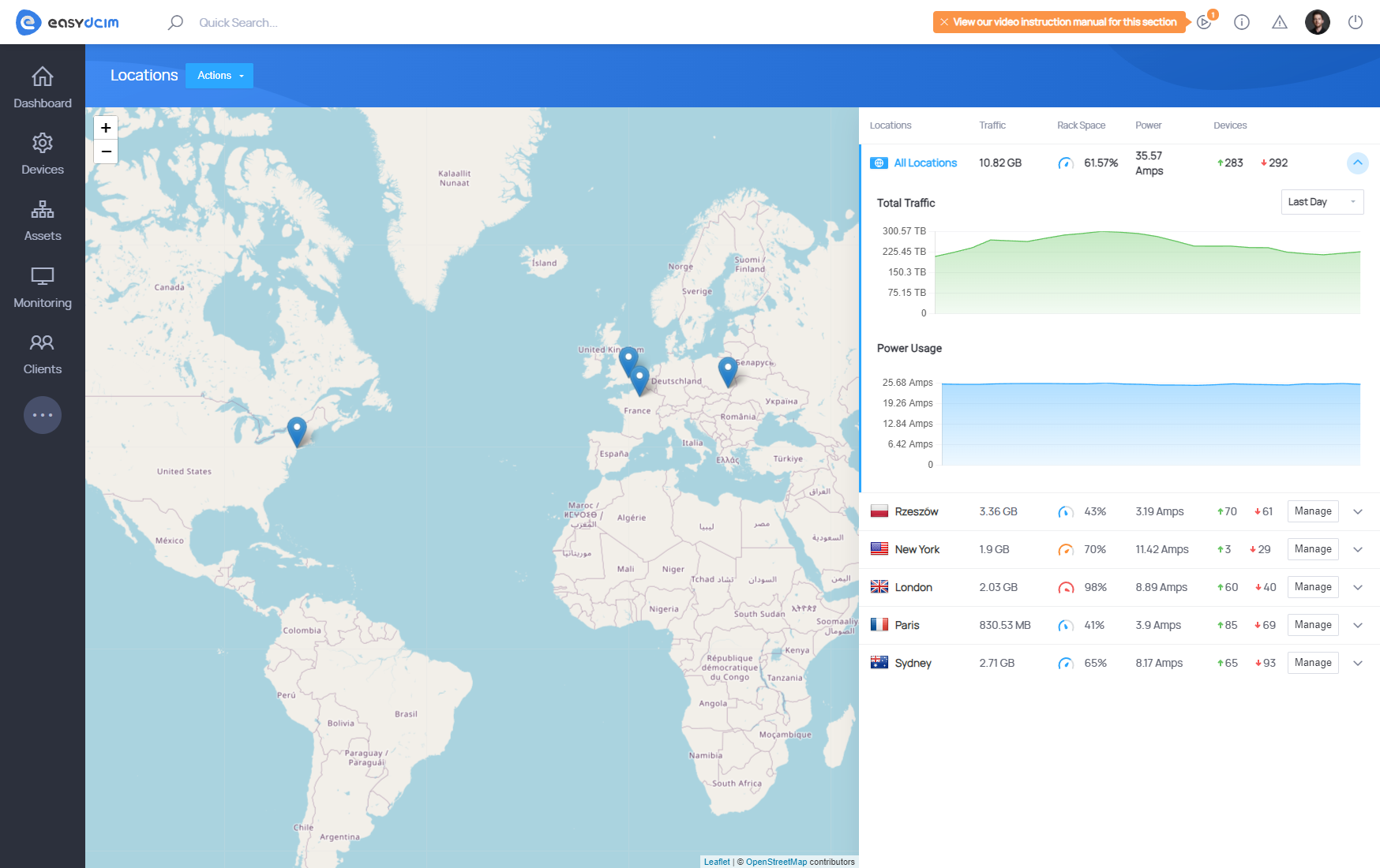
Such added location will be shown on the list of locations. If the location address has been specified, it will appear on the map thanks to the automatically generated coordinates. The section on the right includes statistics on all the locations available in the system and for single locations. The stats represent data such as: data usage, rack cabinet space usage, power consumption and number of ON and OFF servers. Traffic and Usage graphs can be easily filtered based on predefined time frames: Last Day, Last Week and Last Month.
Use the action menu to perform the following actions:
- Add Floor - displays the form which you can use to add a new floor in the location
- Edit - change location data
- Delete - remove the location
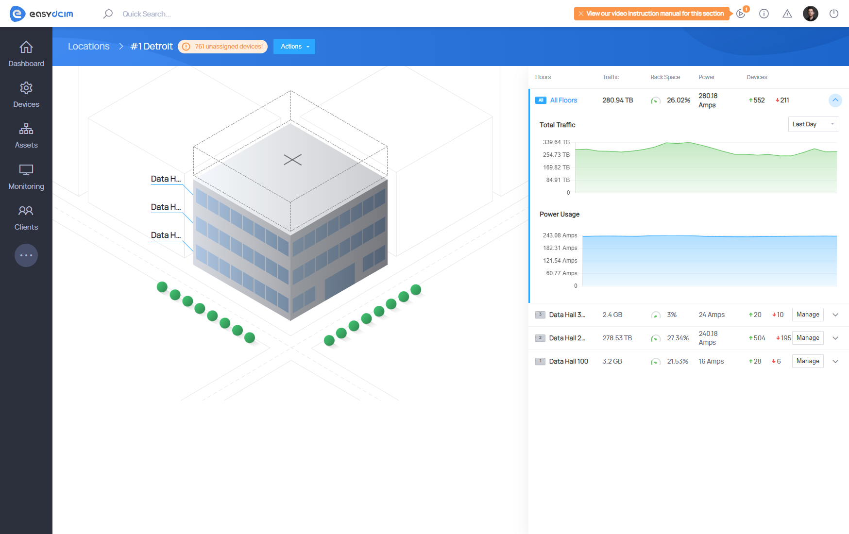
Location summary view displays a building visualization in 2D. To assure the visualization will be generated, you must add at least one floor in a location. Floors in the building have numbers assigned, which lets the visualization represent true view of the building starting from the first floor and ending on the last one.
The section on the right includes statistics on all the floors per location and for single floors. The stats represent data such as: data usage, rack cabinet, space usage, power consumption and number of ON and OFF servers. Traffic and Usage graphs can be easily filtered based on predefined time frames: Last Day, Last Week and Last Month.
Floors management
Floor is one of the elements of the whole network of locations in the system. Every location may include an indefinite number of floors. In order to add a new floor, find the Add Floor in the actions menu. The form includes following fields to fill out:
- Floor Name
- Floor Number - number of the floor, it is generated automatically as a serial number
- Floor Rows - number of rows based on which the grid will be generated
- Floor Columns - number of columns based on which the grid will be generated
Use the ‘Manage’ button to move to the floor summary view, the button is available in the right section.
Floor summary
View of the floor summary is divided into two parts: GRID and statistics. Grid must have a square shape with the same number of columns and rows. The number of columns and rows is used to generate the grid where rack cabinets will be located. Use the action menu to perform below action:
- Add Floor - displays a form to add a new floor to the location
- Add Rack - displays a form to add a new rack to the floor
- Edit - change the floor data
- Delete - remove the floor
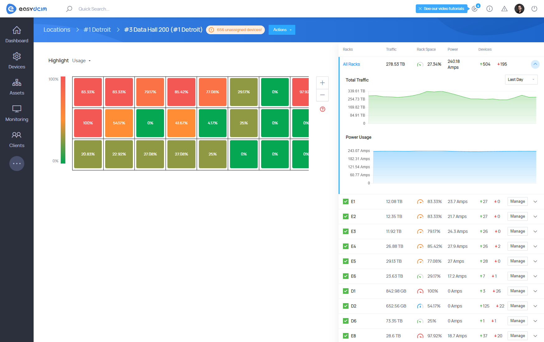
In order to set a rack cabinet on the floor, you must define an adequate place and then press Assign button. The form includes only these rack cabinets that are not assigned yet. After the rack cabinet is successfully assigned, it will be placed in the grid view. Rack cabinets visible in the grid view have adequate colors depending on the selected type:
- Usage - the color defines the space usage in the rack cabinet
- Traffic - the color defines the devices data usage in a rack cabinet
- Power - the color defines the devices power consumption in a rack cabinet
Racks management
Rack cabinets assure the possibility to systematize the devices within one location with racks. Every rack cabinet may be of different size defined previously by the administrator. In order to add a new rack cabinet choose the Add Rack in action menu. The form includes:
- Rack Name - any name of the rack
- Rack Height - Height of the rack defined in the number of rows
- Target Floor - floor where the rack will be located
- Rack Views - defines views available for the rack cabinet
Use the Manage button, located in the right section, to move to the rack summary page.
Rack summary
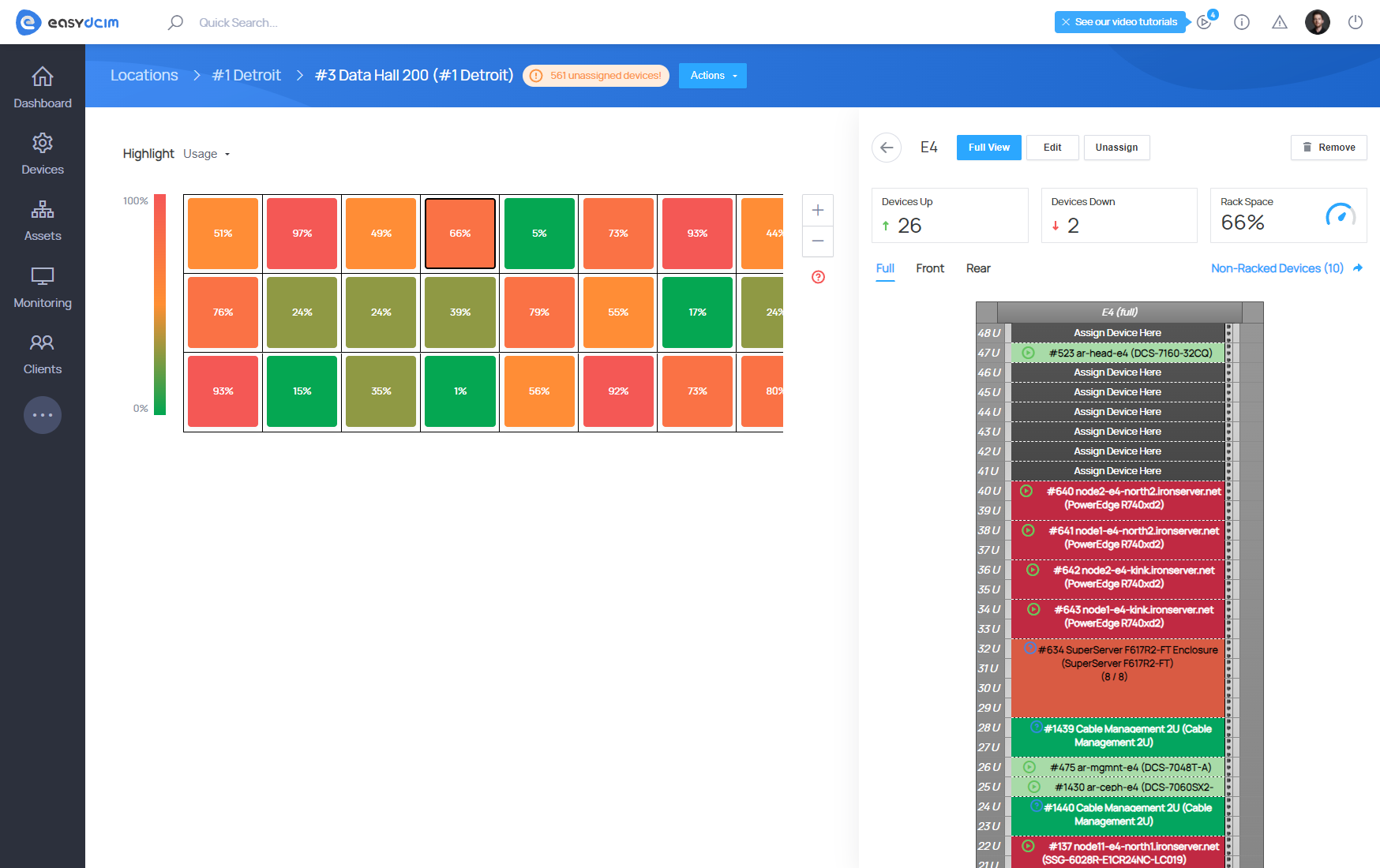
Rack summary page shows the most important statistics on space usage in the cabinet and the number of servers ON and OFF. You may also move to the list of inventory items that are visible next to the rack cabinet (Non-Racked Devices).
Available actions:
- Edit Details - change the rack cabinet data
- Unassign - remove the rack cabinet from the floor grid
- Remove - delete the rack cabinet from the system
In order to place a device on a rack you have to select the row and then press Assign Device Here. Next, in the form, select a device you wish to assign to the rack. Remember that the system calculates free space on a rack by reviewing rows from the top to the bottom. In other words, if you want to assign a device of, for example, 5 units in size at the bottom of the rack, you must select position number 5 and assign the device to it. The system will check if positions number 5, 4, 3, 2 and 1 are free, if yes, the device will be successfully assigned. Keep in mind that devices can be assigned depending on the selected view. To illustrate, in case of Front view, you may assign devices marked as Half Size (Rack Front) only. The situation is similar for Rear view, here only Half Size (Rack Rear) devices can be assigned.
You may use the device edit form to define in which part of the rack cabinet the device will be located. You can find this edit form on the device summary page in the actions menu. The below described fields define the position in the cabinet:
- Device Size (Units) - number of units the device covers
- In Rack Size
- Full
- Half Size (Rack Front)
- Half Size (Rack Rear)
Every element of the rack cabinet can be easily moved with the catch&drop option, thanks to which you may quickly reposition a device between different levels. Colors of single rack cabinet elements depend on the type of the device. In the Item Types & Models section you may define the colors for types such as: Server, Switch or PDU.
Press any element in the rack cabinet to:
- get quick information
- have an option to remove it from the cabinet
- move to its summary page